Features
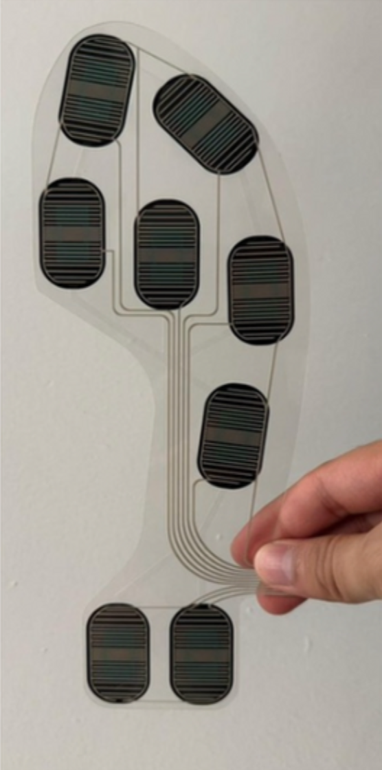
WavGuard uses force-sensitive resistors (FSRs) embedded beneath the rider’s feet to measure how pressure is distributed across the wakeboard. Instead of relying on absolute force values, which vary widely between riders, the system evaluates relative pressure ratios between sensor regions. This allows the system to scale across different rider weights, stances, and skill levels without recalibration.
The board is divided into multiple pressure zones that capture meaningful balance information:
- Toes vs. heels (forward/backward balance)
- Left vs. right side (lateral balance)
- Diagonal corners (rotational imbalance)
At each timestep, raw analog FSR readings are normalized into percentage-based ratios representing how total rider weight is distributed across the board. For example, instead of measuring force in newtons, the system determines whether 60% of pressure is on the toes and 40% on the heels.
This ratio-based approach ensures that feedback reflects how a rider is balancing, not how hard they are pushing. These normalized pressure ratios are then passed to the Code Logic layer, where they are compared against expected values derived from board orientation.
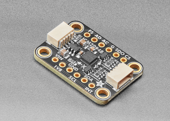

WavGuard uses an inertial measurement unit (IMU) to track the board’s orientation in real time. Specifically, roll and pitch angles are monitored to determine how the board is tilted relative to the water. This information provides critical context for interpreting pressure data from the FSRs.
Raw IMU data is filtered to reduce noise caused by wakes, vibration, and transient disturbances. Short-duration spikes are suppressed so that feedback reflects sustained rider behavior rather than momentary water conditions.
The system defines three tilt-based training zones:
- 0–8° (Balance Mode): The board is considered relatively flat. The system checks for even pressure distribution across all FSR regions and reinforces basic stance awareness.
- 8–20° (Edge Commitment Mode): The rider is intentionally edging. In this range, pressure is expected to shift in proportion to the tilt angle, and feedback teaches riders how to commit weight correctly.
- >22° (Safety Warning Mode): The board is approaching a loss-of-control condition. Large red warnings prioritize rider safety rather than correction.
By using tilt thresholds, the IMU prevents the system from penalizing riders for intentional maneuvers while still identifying unintentional imbalance. IMU data is passed to the Code Logic layer to determine the expected pressure distribution for a given board angle.
The Code Logic layer acts as the central decision-making system of WavGuard. It combines normalized pressure ratios from the FSRs with orientation data from the IMU to determine when feedback is necessary and what form it should take.
For each timestep, the system calculates an expected pressure ratio based on board tilt using linear interpolation. For example:
- At 0° tilt, expected pressure is evenly distributed (≈50% toes / 50% heels).
- At 15° toe-side tilt, the system expects ~70% of pressure on the toes.
- At higher tilt angles, expected ratios shift accordingly.
Actual pressure ratios from the FSRs are compared against these expected values. If the mismatch exceeds a predefined tolerance, visual feedback is generated. This prevents constant feedback during minor fluctuations and focuses attention only on meaningful errors.
LED feedback follows three clear rules:
- Blue: Not enough pressure in a region
- Red: Too much pressure in a region
- Green: Appears only when pressure distribution and board orientation are in equilibrium
Balanced regions remain unlit to minimize distraction. Green is not intended as a constant target; rather, it indicates moments of equilibrium. The system is designed as guidance, recognizing that certain riding maneuvers naturally require imbalance.
To ensure stability and usability, pressure data is debounced, IMU signals are filtered, and feedback updates are rate-limited. Together, these design choices create a responsive yet non-intrusive training system that accelerates learning without overwhelming the rider.
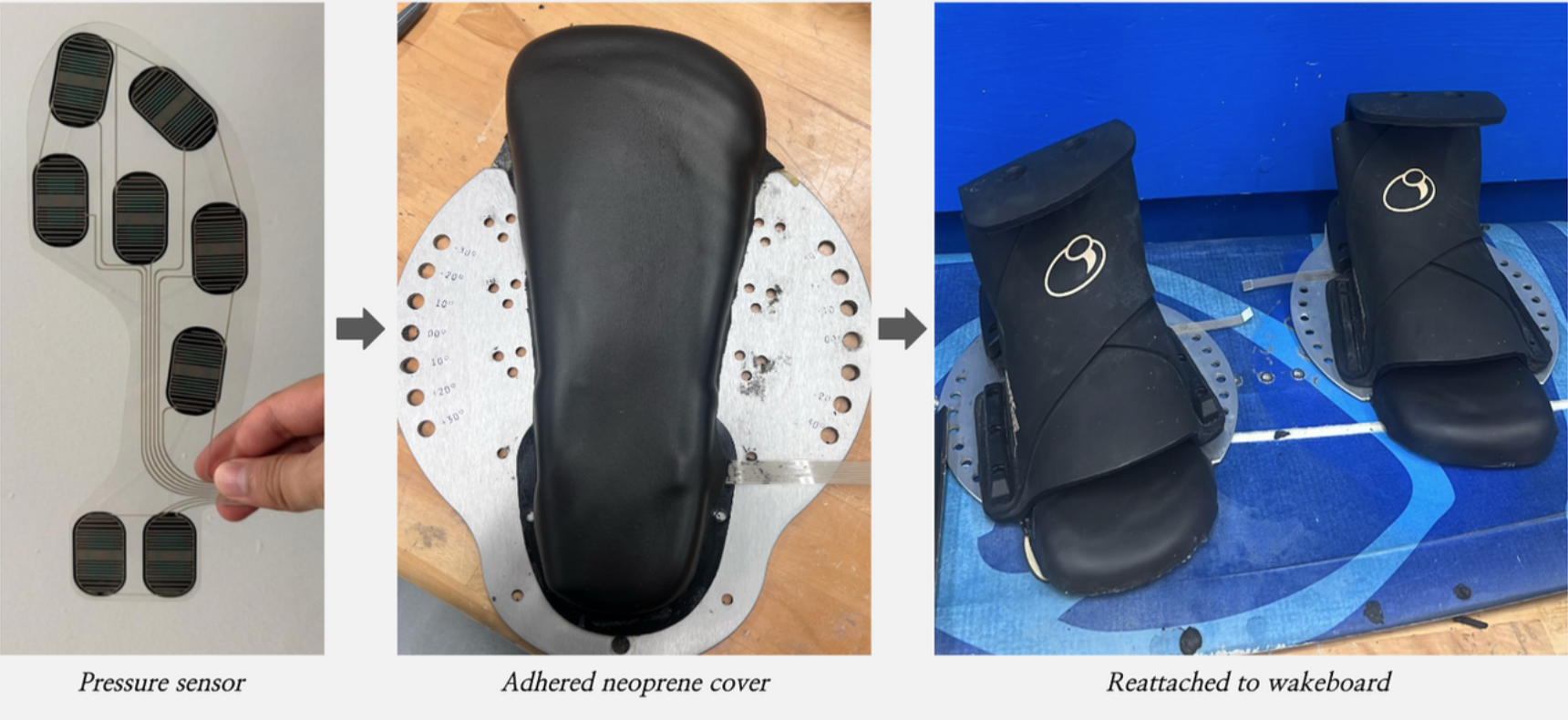
RTV silicone and marine-grade sealant are used to attach the LEDs, seal joints, and waterproof the wiring entry points.
- Gasketed electronics box
- Marine-grade connectors
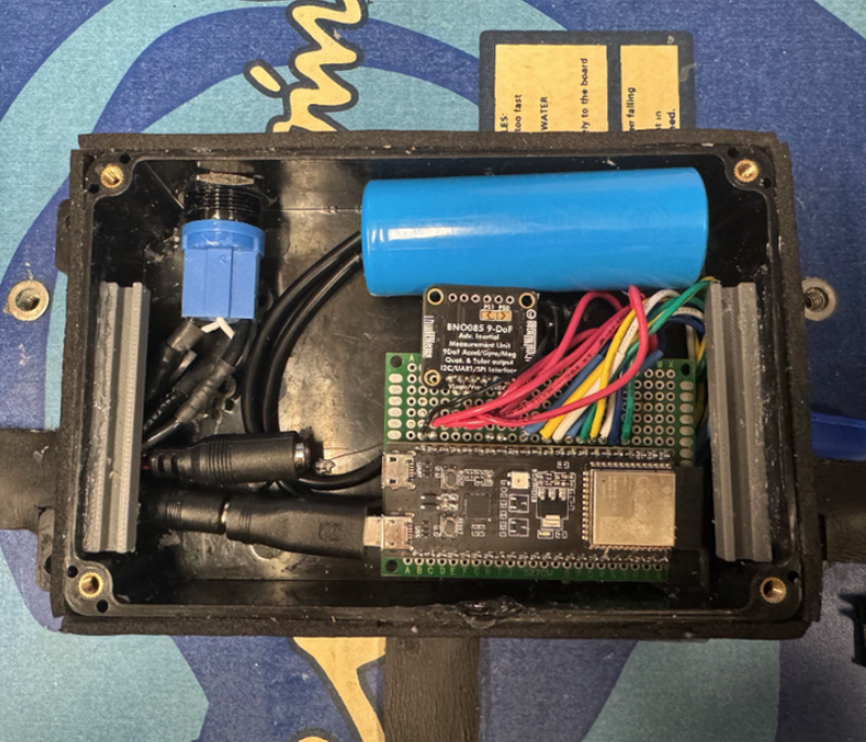
An IMU is placed in the center electronics box to measure board tilt and angle.
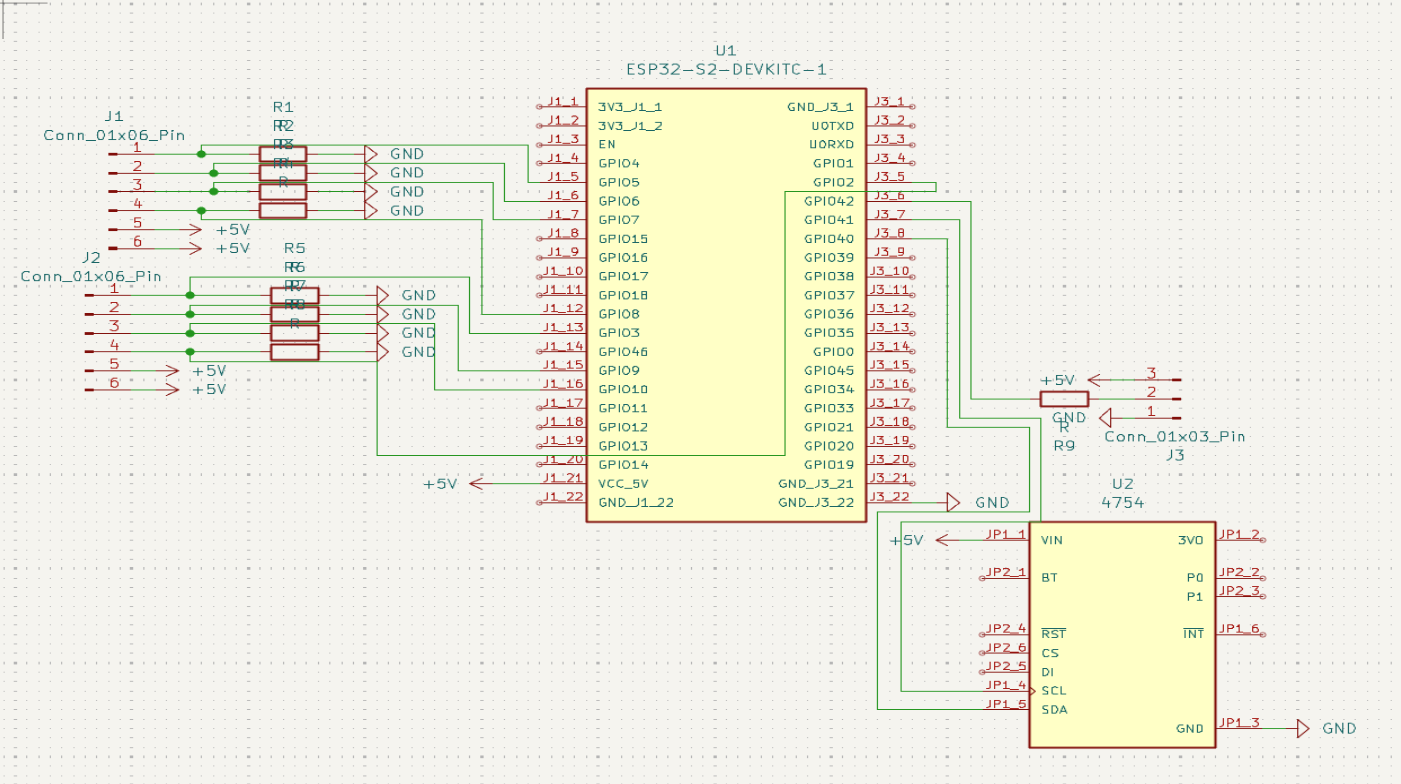
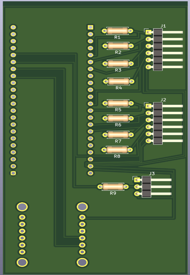
An IP65-rated waterproof ABS enclosure with an O-ring seal houses the ESP32, IMU, FSR circuitry, and LED resistors. The enclosure is mounted with threaded inserts for secure attachment and easy service access.
- Removable and rechargeable battery
- Exterior on/off button
- Cushioned mounting (neoprene) to isolate shocks and prevent collisions
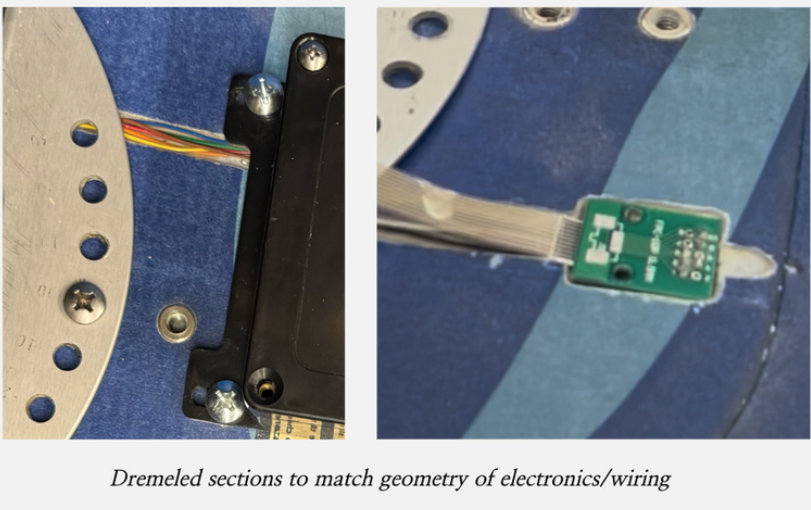
To create a clean, finished board with no exposed electronics, we used a Dremel to machine custom wiring channels directly into the board. These channels route power and signal lines beneath the foot pads, connecting the electronics box to the foot sensors and LED system while keeping all wiring inaccessible to the rider.
After routing, the channels were filled with potting gel and waterproof epoxy to lock the wires in place and provide long-term water resistance. This process prevents wire movement under flex and ensures durability in repeated water exposure.
- Wiring embedded below the board surface
- Potting gel and epoxy for waterproofing and strain relief
- All wiring hidden beneath foot pads for safety and aesthetics
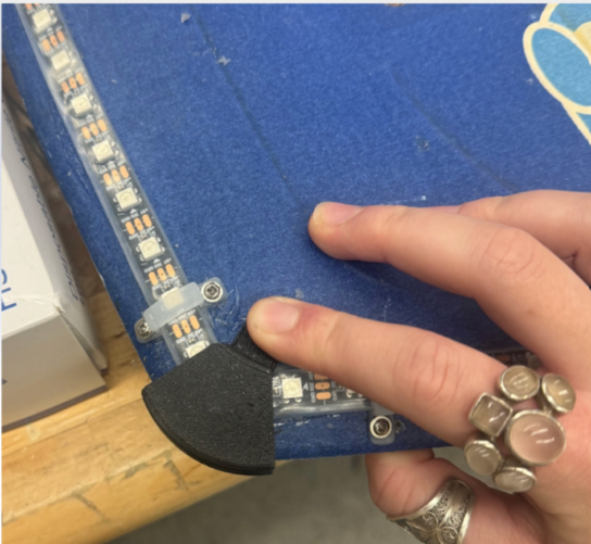
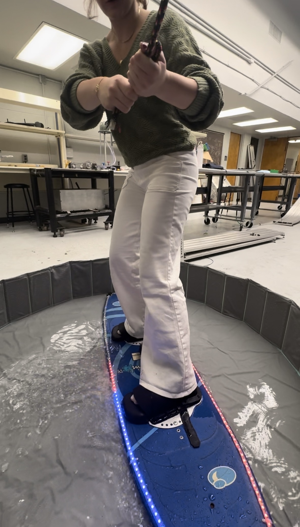
Individually addressable LED strips were mounted along the perimeter of the board to provide immediate, intuitive visual feedback. LEDs were placed where they remain visible to the rider without interfering with stance or movement.
Custom 3D-printed corner brackets were designed to secure the LED strips and protect both the board edges and electronics from impact during falls or transport.
- Individually addressable LEDs for zoned feedback
- Edge-mounted placement for high visibility
- 3D-printed corner brackets for protection and durability